Rabbit circuit soldered up
So - the solder breadboards arrived today so I soldered up the circuitry. I've switched to using parasitic power mode for the 1-wire temperature sensors (DS18B20's). To do this you tie both power and ground pins to ground, and add a 4k7 ohm resistor as a pull-up resistor between the data pin and 5v.
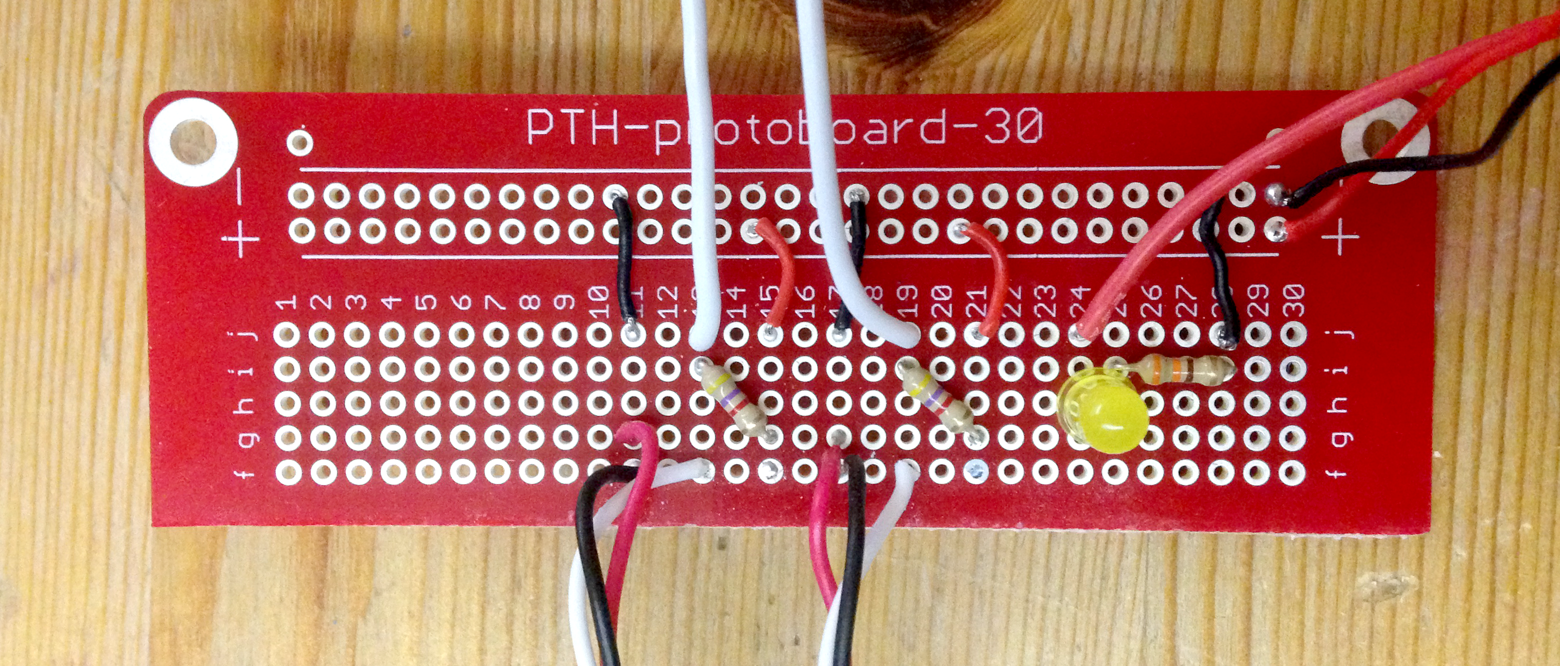 Circuit wired up in parasitic power mode
You can also run the devices in non-parasitic mode (they can return results faster in non-parasitic mode) but this requires three wires instead of two. You still need the pull-up 4k7 resistor too (this took me a while to figure out when I was testing).
To change this circuit to non-parasitic requires moving two wires. See the arrows in the next graphic.
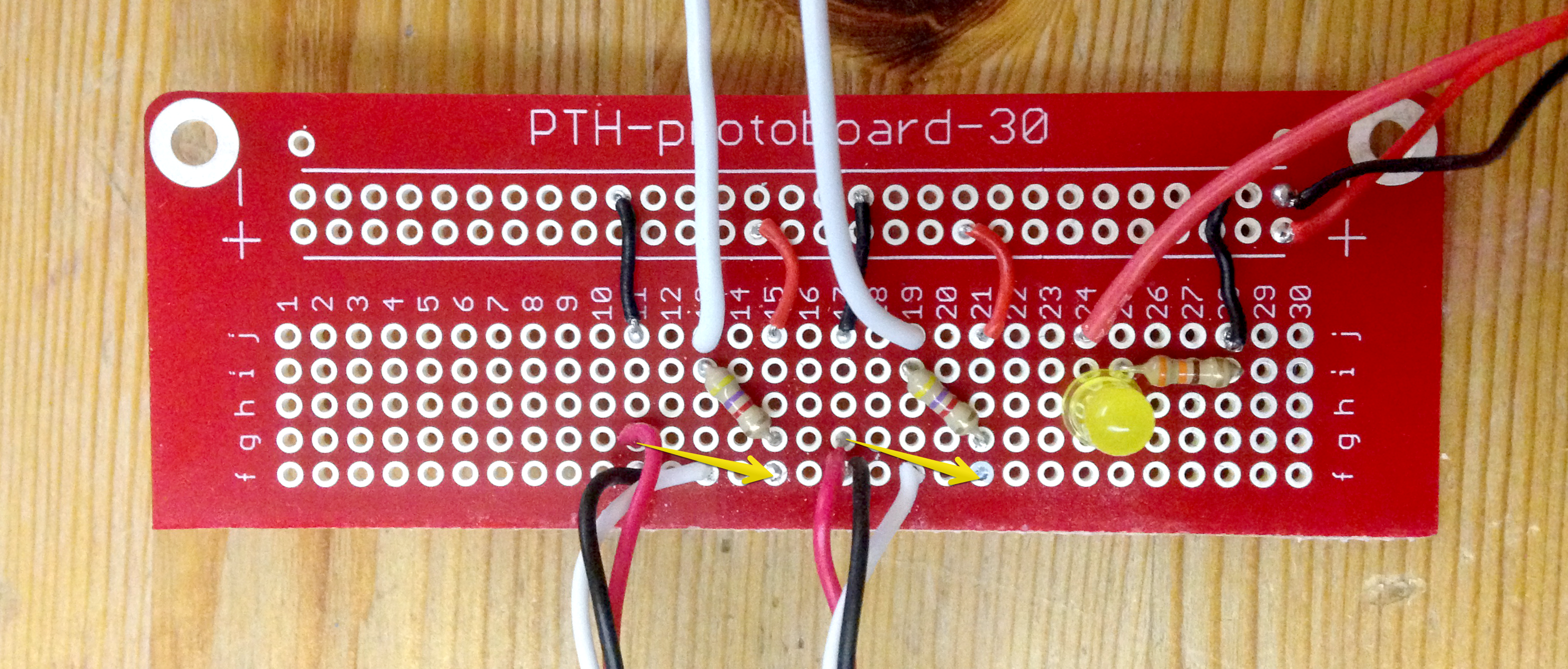 Change required to switch to non-parasitic power mode
I do have one issue I can't solve right now.
If I connect this to a PoE switch then it takes power via the ethernet cable and it gives results - but the actual Arduino Uno card gets extremely hot - this chip next to the power input connector:
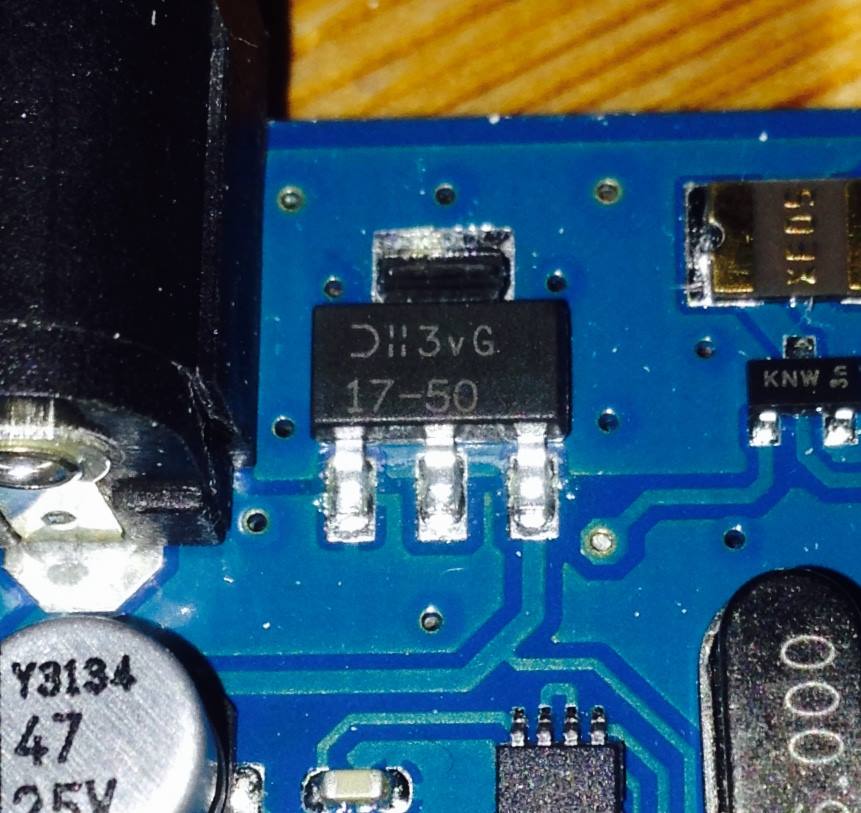 Chip that gets hot
If I connect the ethernet cable to a non PoE port and give the arduino power via USB then it does not get hot.
This annoys me somewhat - I chose the PoE ethernet shield so that I could still get temperature readings even if the power to the heaters failed - but I guess I can live with it while I try to find out what's going wrong - I can always trigger an alert based on "no data available" instead of a too low temperature.